
Forget about ancient analog potentiometer circuit and build your own digital O2 analyzer based on Arduino compatible board!
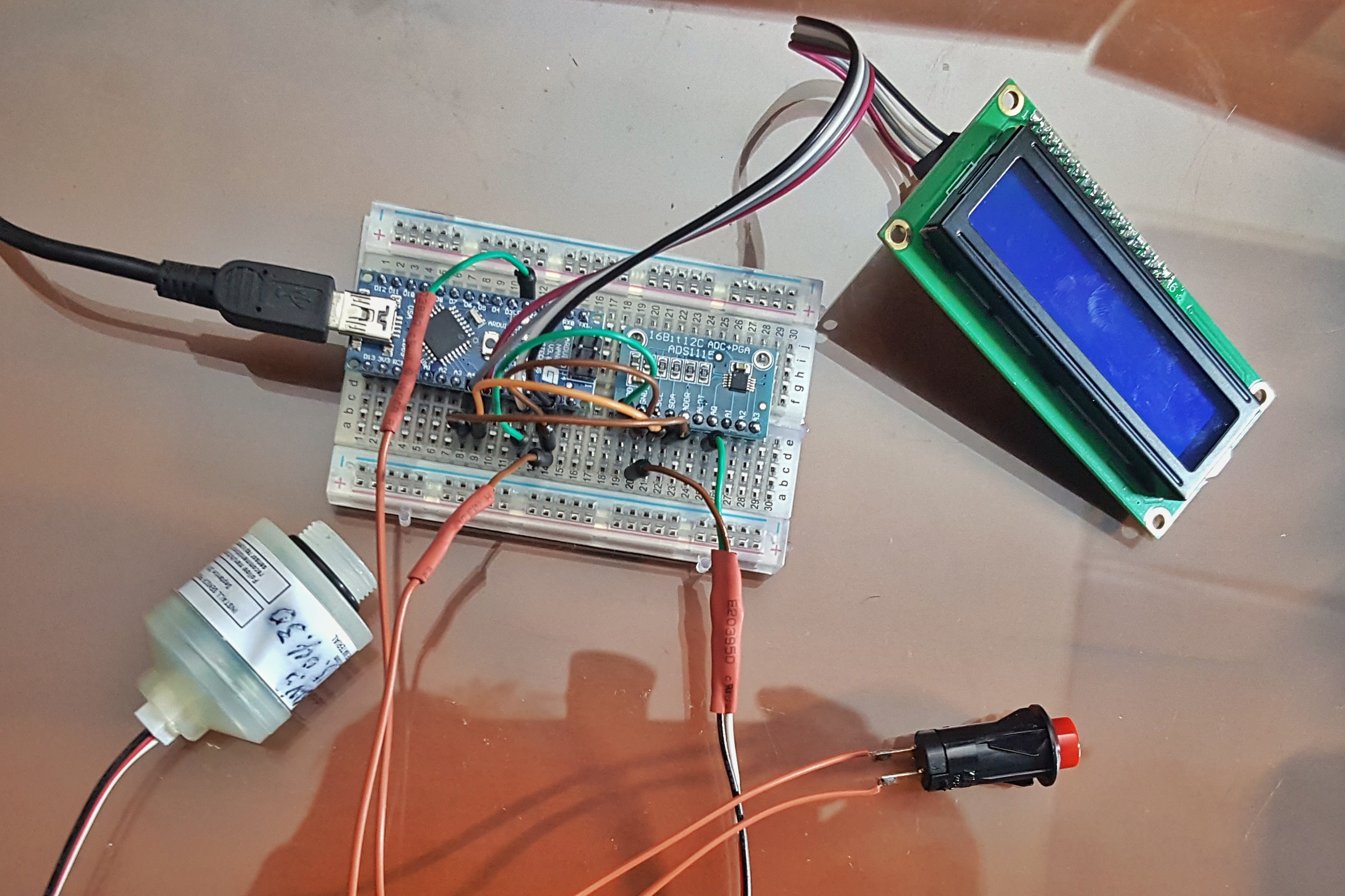
Part list
- Arduino nano compatible board (or any other Arduino board will do)
- ADS1115 16 Bit DAC Module (the ADS1115 provides 16-bit precision at 860 samples/second over I2C!)
- LCD 1602 I2C module
- 1 Push button
- O2 sensor (I use old cell from my CCR but you can get sensor from Teledyne, Maxtec or other manufacturer)
- Connector for o2 sensor
Wiring
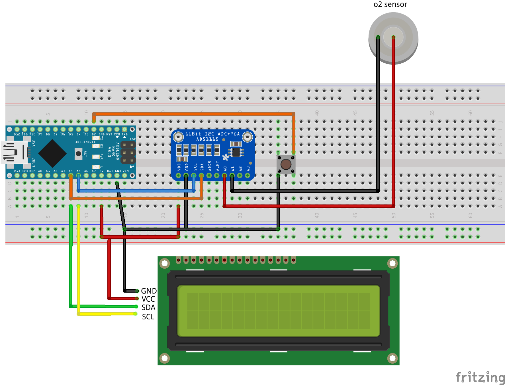
ADS1115
- VDD to 5v
- GND to Ground
- SCL to A5 (nano)
- SDA to A4 (nano)
LCD 1602 + I2C module
- GND to Ground
- VCC to 5v
- SCL to A5 (nano)
- SDA to A4 (nano)
Push button
- 1 pin to Ground
- 2 pin to D2 (nano)
Oxygen sensor
- positive to A0 ADS1115
- negative to A1 ADS1115
The source
Additional library require.
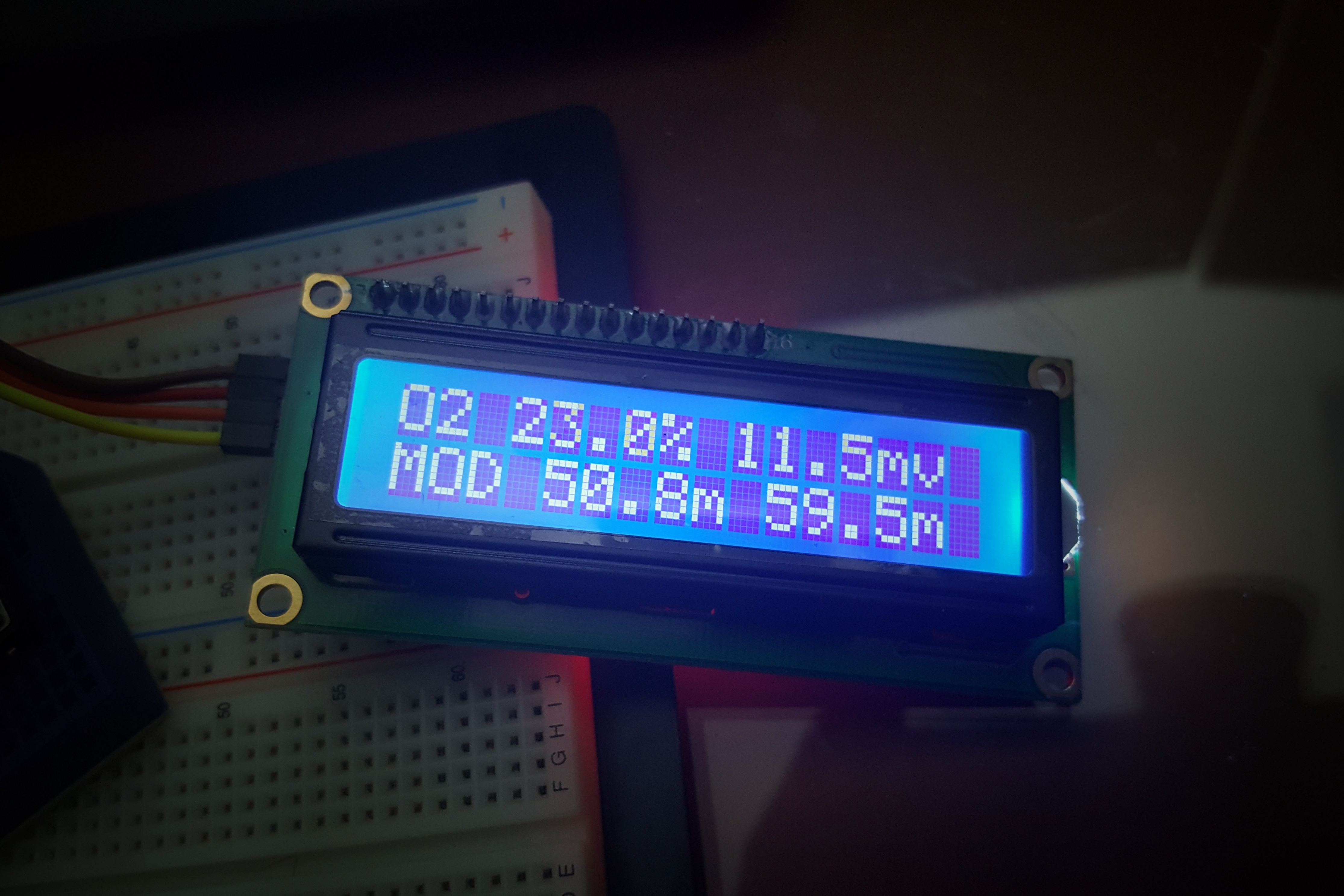
The code is very simple. Calibration and storing millivolt output from o2 sensor (in the air – o2 20.9%) when button is pressed.
Oxygen percentage and millivolt of sensor will display on LCD.
Note
- In many case i2c device address are different from the code. If something not working then check your i2c address (ads1115 and lcd module) using i2c scanner.
Update 28th Feb 2017
- Reading sensor function changed from Single Ended to Differential Conversion. Sensor out should be connected to A0 & A1 (ads1115) accordingly.
Update 22th Feb 2017
- Button need push & hold for 2 sec to calibration.
- Display MOD (Maximum Operating Depth) : po2 1.4 & 1.6
Hi, I tried building this but I`m getting zero mV from the sensor…?
Hi sir can u make another project with gasboard 7500e