
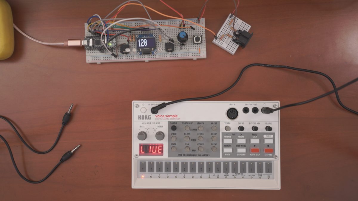
DIY Arduino MIDI master clock/sync/divider for MIDI instruments, Pocket Operators and Korg Volca.
You can easily find similar projects but I added ability to sync different PPQN via 2nd 3.5mm trs jack (check-out demo video below).
MIDI & 1st audio jack sync according to BPM and I can adjust different PPQN with encoder (push once) for 2nd audio sync jack.
I want to add swing function (like Volca Sample) but still figuring out best way to implement (maybe future updates).
Code is not well-documented and anywhere near neat. Any suggestions are welcome. :)
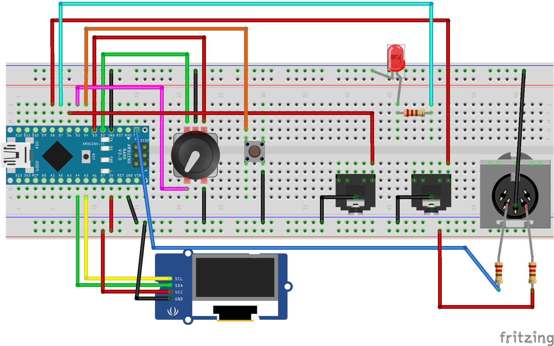
Part list
- Arduino (any model)
- 1 x Push button (You can omit this and use encoder’s button. Need implement long & short push button code)
- 1 x Rotary encoder with button
- 2 x 3.5mm trs female socket (You can add more if you need)
- 3 x 220 ohm resistor
- 1 x MIDI connector (5-pin standard DIN)
- 1 x Led
- 0.96 inch OLED 128×64 I2c display module (LED module is slow you can use other display like “16×2 LCD”)
The code
How to use
- Change BPM via encoder
- 1 Push encoder button to change 2nd audio sync speed, push again to exit to main BPM display
- Start / Stop via Push button
This was exactly what I was looking for, thank you for putting this together and sharing with us, cheers!!
Hi
This looks awesome, almost what I was looking after! :-)
I want to send sync via USB midi, send transport commands start/stop, and “rec” commands via foot switch jack to my Livetrak L-12, I am planning to use a Teensy 3.5 for this.
Can you elaborate a bit regarding the audio sync, I presume it is not standard midi sync in that jack?
Keep up the good work!
May I ask you which rotary encoder we have to use?? A standard one or a specific reference?? The button is for start/stop function. isn’t it?
Thank you very much
Andrea
Hello
I just finish the project using the Arduino Uno R3 i got in a basic starter kit from Amazon . The pin connections on my arduino are not in the same position of the NANO one which is present in the original project , but of course i respect the connections shows in the diagrams ( in/out pins are not in the same order in each side , but I think is the same and it should works anyway). Because I wasn’t not completely confident about the breadboard jumpers connections I decided to solder everything to be 100% sure not to do a mistake. Now my problem is to upload the code on the board by using a MAC . An error always occurred … Does anyone have the same issue?? I plug the PCB to the USB cable and the green light is on but also a yellow one. The COM port seems to be recognized by the OS . I also tried to push the reset button
Do I need to update the UNO R3 by specific drivers for the MAC?
Do I use a different programs for MAC users instead of classic IDE ?
I don’t know how to solve the problem and I’m in trouble deep
Thank’s to you all
Andrea Fabri
I’m having the same problem but using windows. I’ve tested all connections with meter. Maybe code problem?
thanks so much, this project is really what I was looking for. May be adding a divider would be a plus…and a midi clock in.
Any idea how many MIDI devices I could drive with this? I am guessing quite a lot because it is only driving onto couplers, I’m just thinking to make one of these with maybe 6 MIDI jacks so I can drive a number of synths / drum machines at once
Currently I have 3 midi outputs without problem. Simply duplicate output circuit and feed it from same tx pin on arduino.
I still haven’t figure out how the PPQN editing works.
How does the:
if (audio_sync2 > 64 || audio_sync2 < 2) {
audio_sync2 = 12;
}
correlate with the +10/ -52 shown when turning the encoder?
I put my code on GitHub today: https://github.com/CrowStudio/DHM
Help much appreciated :-)
Hi i loved this, I only have a question, i see that this clock works really good specifically for volcas and PO’s but if I would want to sync an ios nanoloop (that can be synced by midi but i think it just works if you use a USB cable, because i tried to use the trs jacks and it didn’t worked). How i should make my conections?, should the code be modified too?
I have a doubt, what kind of potentiometer is it? in the schematic I see a 5 pin potentiometer, I can’t figure out which one I need.
it’s not potentiometer. Try google it “push button rotary encoder”.
Hi. are possibile male clock output for eurorack?
Hello! thank you for this post. I made a project that had to be connected to a 12v modular, I first tested your prototype with a UNO, and everything worked fine, then I got a NANO and built the whole project.
Because of my stupidity, I made a mistake in the screen connections and put the VCC on the GND and vice versa and connected it for several seconds several times until I realized what was happening (nothing was happening except that the arduino was connected), then I reversed the screen connections, but it seems to me that it was damaged.
Although the screen worked (badly) with the u8g2 program test, the screen never worked again with the project and so neither did the project (I re-did it again on a breadboard with the UNO as before but … nothing).
my question is : is it possible that the project doesn’t work just because the screen is damaged?
thanks
Translated with http://www.DeepL.com/Translator (free version)
How to use: “16×2 LCD” ? This sketch don`t work with LCD display!
You need to use the appropriate library, have you tried to search the internet/Arduino forums on how to get your display working? 😉
it doesn’t work, please help. I don`t understand your sketch for make changes
I have the required libraries, verified code and uploaded. Powers on fine but the encoder is not working when I turn it. Push button on encoder works fine. What could be the problem? I’m new to this.
Hey! Whats up?
Thanks for sharing this project, it works great! You said in one of the commentaries above that it’s just duplicate the midi output circuit from the same tx arduino pin if more MIDI outs are required, right?
Does that works the same for the clock out from the trs? Can I add more outputs to the pins D6 and D8?
It worked great with my volca bass and novation mininova, but I also have a DIY analog modular that runs on 12V.
I have some sequencers in it that use clock in based on the chips CD4040 and CD4051. The LFOs from the modular generates peak gates of 12V. Is there a way to make the clock outs from the arduino to also sync those CD4040 and CD4051 chips? This is my first time using arduino, so I kinda lost!
Thanks! Awesome project
I have been trying to code adding midi clock slave capability to my homemade arduino Uno and Nano midi projects. Everything I have tried compiles but does not work. I would like to have this Master Clock control the tempo start and stop of my midi projects. Does anyone know a simple code to add to my projects to do this? I have been working with OFXMidiClock,midilabs, u-clock,etc. Seems like it would be possible with the Midi Library using the void handleClockFunction, current clock,last clock, with timing clock 0xF8, start 0xFA,continue oxFB,stop 0xFC. So far not able to find the correct code structure. Any help would be greatly appreciated!!!